Electricity (class10)
Take the QuizDiscovery of Electricity
The invention of electricity was not the work of a single individual, but rather a series of discoveries and innovations over centuries that laid the foundation for our modern understanding and use of electrical energy. The earliest recorded observations of static electricity date back to ancient Greece, where philosopher Thales of Miletus noticed that amber, when rubbed with fur, could attract lightweight objects. However, it was in the 17th and 18th centuries that significant progress began, with scientists like William Gilbert studying electric and magnetic forces and enjamin Franklin famously demonstrating that lightning was a form of electricity through his kite experiment. In the 19th century, breakthroughs by pioneers such as Alessandro Volta, who invented the first electric battery (Voltaic pile), Michael Faraday, who discovered electromagnetic induction, and Thomas Edison, who developed the practical electric light bulb, helped electricity transition from a scientific curiosity to a transformative force powering homes, industries, and communication systems. These contributions collectively represent the invention and harnessing of electricity, which revolutionized human life and laid the groundwork for the modern technological era.
Electricity and Circuit
Electric current is the flow of electric charge in a given unit of area of a conductor. Electricity is produced due to the movement of electrons from one point to another point of a conducting wire or any body. The SI unit of electric current is the ampere (A), named after the French scientist Andre-Marie Ampere. Current flows in a circuit when there is a potential difference (voltage) between two points and a closed conducting path that allows charges to move. This potential difference is usually provided by a cell or battery. A simple electric circuit consists of a source of energy (like a battery), conducting wires, a load or appliance (such as a bulb or resistor), and sometimes a switch to open or close the circuit. The direction of conventional current is from the positive terminal of the battery to the negative terminal. The phenomenon of electricity is nbetter understood with the help of Ohm's Law. Ohms law states that the current (I) flowing through a conductor is directly proportional to the voltage (V) across it and inversely proportional to its resistance (R): I = V/R
⚡ Properties of Electric Current
- Electric current is the flow of electric charge (usually electrons) through a conductor.
- It flows from the positive terminal to the negative terminal (conventional current direction).
- The SI unit of current is ampere (A).
- Electric current requires a closed path (circuit) to flow.
- It can produce heat, light, magnetic field, and chemical changes.
- The current depends on the potential difference and resistance of the conductor.
- Electric charge is conserved and quantized (measured in coulombs).
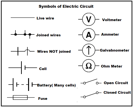
🔧 Common Devices Used in Electric Circuits
Types of Circuits
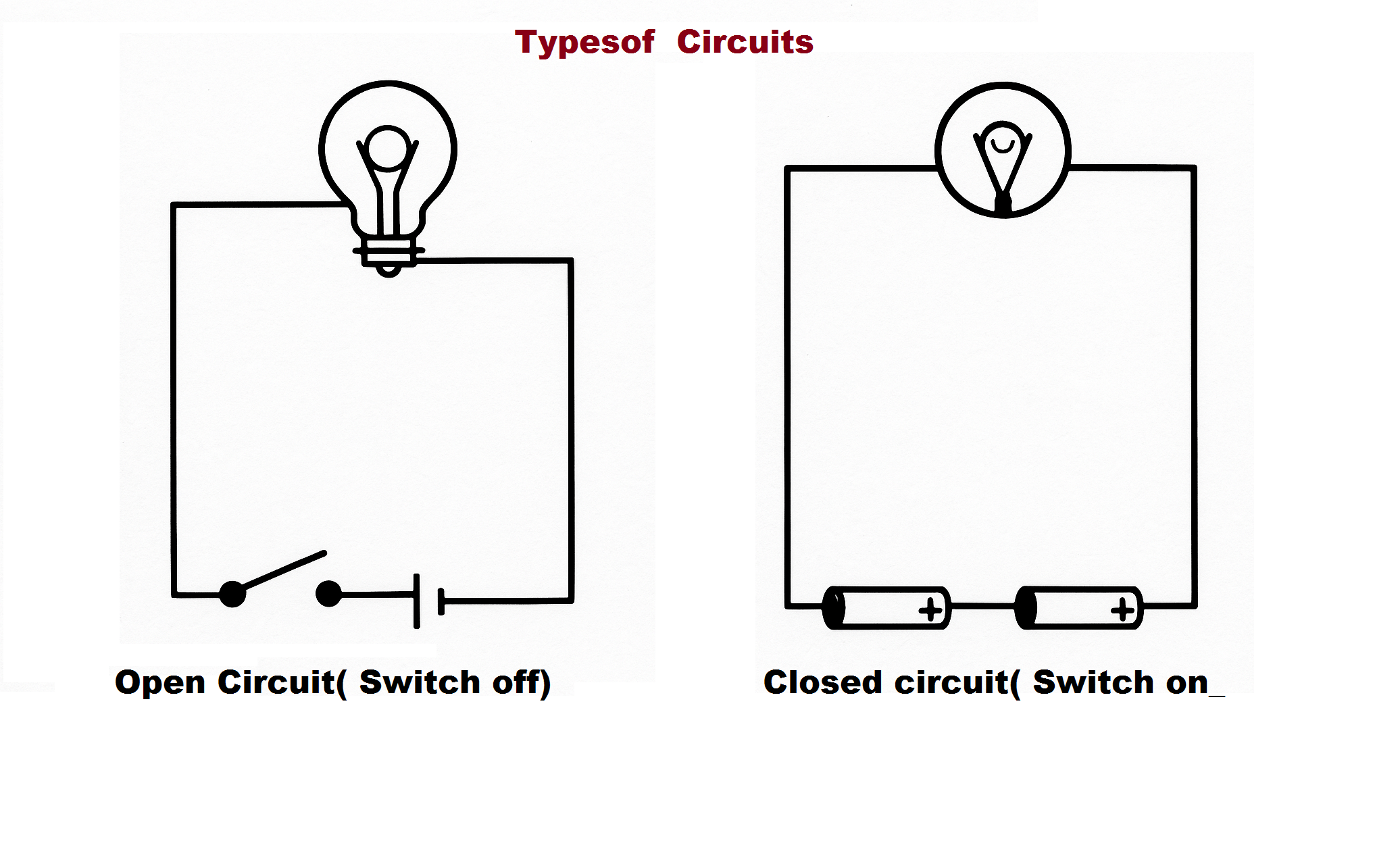
In a closed circuit, when the switch is "on," the circuit is complete and current flows. On the other hand, if the switch is "off," the circuit is said to be open and current does not flow. Proper circuit diagrams using standard symbols for cell, battery, resistor, bulb, and switch help to represent electric circuits clearly and are an essential part of understanding electric current at the 10th-grade level.
Electric Potential and Potential Difference
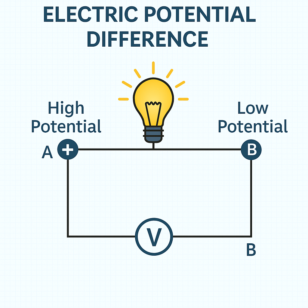
In the study of electricity, electric potential at a point refers to the amount of electric potential energy per unit charge at that point in an electric field. It is a measure of the ability of the electric field to do work in bringing a unit positive charge from infinity to that point. The SI unit of electric potential is volt (V), named after Alessandro Volta.
Definition of Electric Potential
Electric potential at a point is defined as the work done in bringing a unit positive charge from infinity to that point against the electric field. It is a scalar quantity.
Important Formulas – Electric Current
| Sl. No | Formula Name | Formula | Units |
|---|---|---|---|
| 1 | Electric Current | I = Q / t | I → Ampere (A) Q → Coulomb (C) t → Second (s) |
| 2 | Charge | Q = I × t | Q → Coulomb (C) |
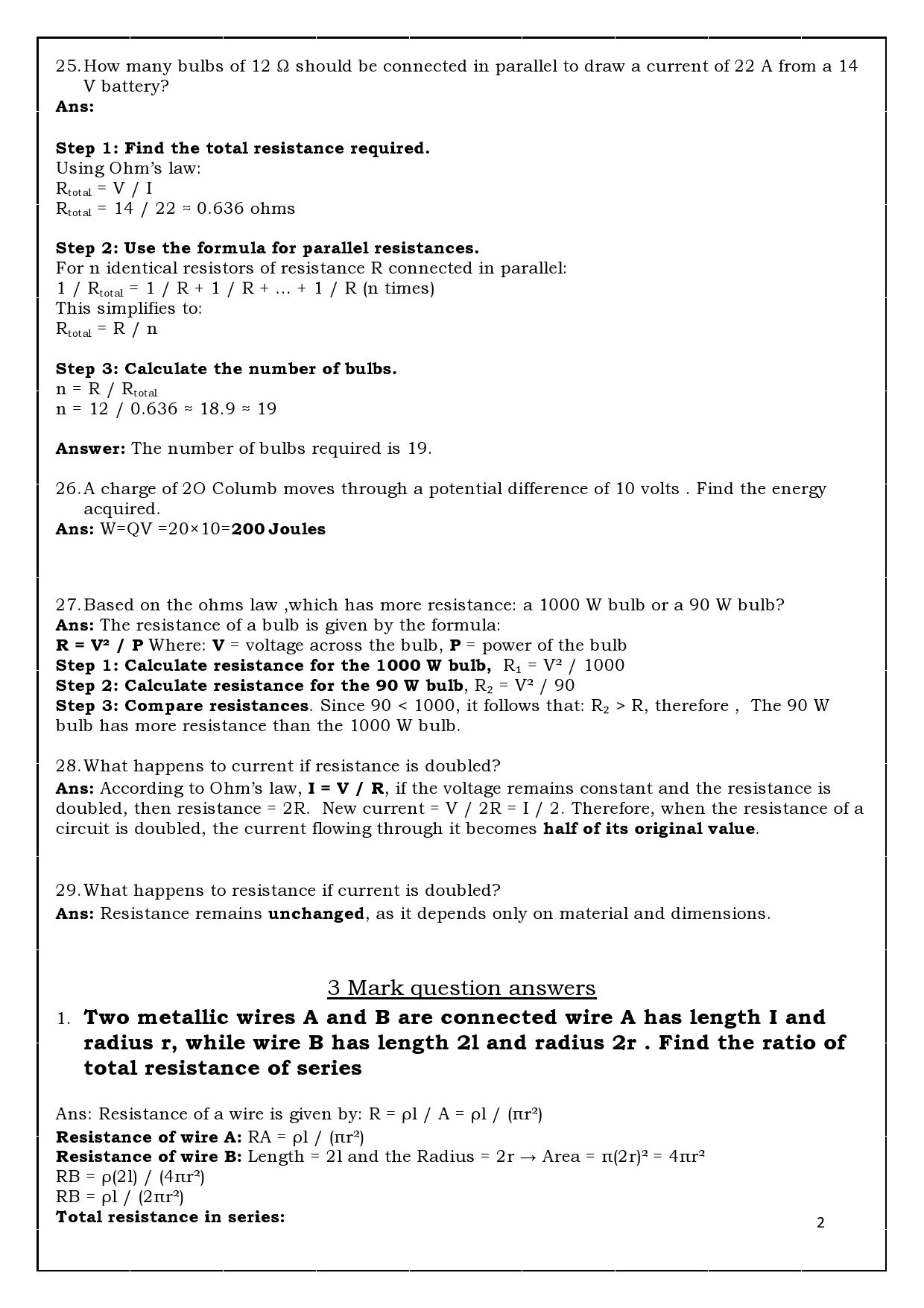
| 3 | Ohm’s Law | V = I × R | V → Volt (V) I → Ampere (A) R → Ohm (Ω) |
| 4 | Resistance | R = V / I | R → Ohm (Ω) |
| 5 | Electrical Power |
P = V × I P = I2R P = V2 / R |
P → Watt (W) |
| 6 | Electrical Energy |
E = P × t E = V × I × t |
E → Joule (J) |
| 7 | Commercial Unit of Energy | 1 kWh = 3.6 × 10⁶ J | kWh (Unit) |
| 8 | Resistance in Series | Rtotal = R1 + R2 + R3 + ... | Ohm (Ω) |
| 9 | Resistance in Parallel | 1 / Rtotal = 1 / R1 + 1 / R2 + 1 / R3 + ... | Ohm (Ω) |
| 10 | Heating Effect (Joule’s Law) | H = I2 R t | H → Joule (J) |
| 11 | Potential difference | V=W/Q | W= work Done and Q=charge in Columbs |
| 11 | Resistivity | p=RA/L | R=Resistance of wire, A=Cross sectional area of wire, L=Length of the wire ) |
Electric Potential Difference
Potential difference between two points in an electric field is the work done in moving a unit positive charge from one point to the other. It causes electric current to flow in a conductor. The SI unit of potential difference is also volt (V).
Reasons for Potential Difference
- Electric Field: Created between two terminals of a cell or battery.
- Work Done: Moving charges against the electric field requires energy.
- Chemical Reaction: Inside the battery causes a buildup of charges at terminals.
- Charge Imbalance: One terminal becomes positively charged, the other negative.
- Maintained Continuously: The battery continuously maintains the difference by doing chemical work.
Formula: V = W / Q
Where:
- V = Potential difference (Volt)
- W = Work done (Joule)
- Q = Charge (Coulomb)
Example
If 10 joules of work is required to move 2 coulombs of charge between two points, the potential difference is:
V = W / Q = 10 / 2 = 5 volts
Importance of Potential Difference
- It drives current through a circuit, like pressure pushes water through a pipe.
- It determines how much energy each charge will carry across the circuit.
- It is measured using a voltmeter, which is connected in parallel to the circuit component.
Basic terms used in electricity
1. Electric circuit: It allows electricity to flow through it and is used to provide electricity for various purposes such as running electric motors, providing electricity to a bulb or a fan, generating heat. Open circuit: is when the key or switch is off where the 2 terminals are not connected to each other, whereas , in the Closed circuit,the key is closed or switched-on which provides a continous channel for the flow of current.
2. Battery: Battery is a combination of two or more cells. The positive terminal of one cell is connected to the negative terminal of another.
3. Terminals: There are two terminals, positive and negative terminals. Current always starts from positive terminal and ends at negative terminal. To make a working circuit, the terminals must be arranged as +,-,+,- …….
4. Fuse: It prevents damage to electric circuit. It acts as a safety device.
5. MCB: MCB stands for miniature circuit breakers. MCB is a switch which automatically turns off when current in a circuit exceeds the safe limit.
6. Switch: A switch is simply a circuit breaker. When you want to stop your work, just shut off the switch.
Symbols Used in Electric Circuit
| Component | Symbol | Description |
|---|---|---|
| Cell | | - | Long and short lines for + and - |
| Battery | | - | - | Multiple cells connected |
| Wire | ------ | Straight connecting line |
| Open Switch | -- / -- | Break in contact |
| Closed Switch | -- o -- | Continuous wire with switch closed |
| Bulb (Lamp) | ( x ) | Circle with cross (glowing filament) |
| Resistor | /\/\/\ | Represents resistance |
| Variable Resistor | /\/\/\ ? | Resistor with arrow through it |
| Ammeter | (A) | Measures current, in series |
| Voltmeter | (V) | Measures voltage, in parallel |
| Ground | GND | Earth connection |
Conductors and Insulators
Conductors are materials that allow electric current to flow through them easily. This is because they have free electrons that move and carry the current. Most metals are good conductors.S Some examples of Conductors are Copper (used in wires),Aluminum (used in power lines. Insulators are materials that do not allow electric current to flow through them easily. They resist the flow of electricity and are used to protect us from electric shocks.Rupper, paper, plastic are some examples of insulators.
Conductors and Insulators
| Material | Type | Common Uses | Conductivity | Safety |
|---|---|---|---|---|
| Copper | Conductor | Electrical wiring, circuits | Very High | Needs insulation |
| Aluminum | Conductor | Transmission lines, cables | High | Needs insulation |
| Iron | Conductor | Electric motors, appliances | Moderate | Needs coating |
| Gold | Conductor | High-end electronics, connectors | Very High | Expensive but efficient |
| Plastic | Insulator | Wire coatings, switches | None | Very Safe |
| Rubber | Insulator | Gloves, mats, insulation tools | None | Excellent Safety |
| Wood (Dry) | Insulator | Handles, board bases | Low (only when dry) | Safe if dry |
| Glass | Insulator | Support structures in transmission | None | Very Safe |
Battery in a Circuit
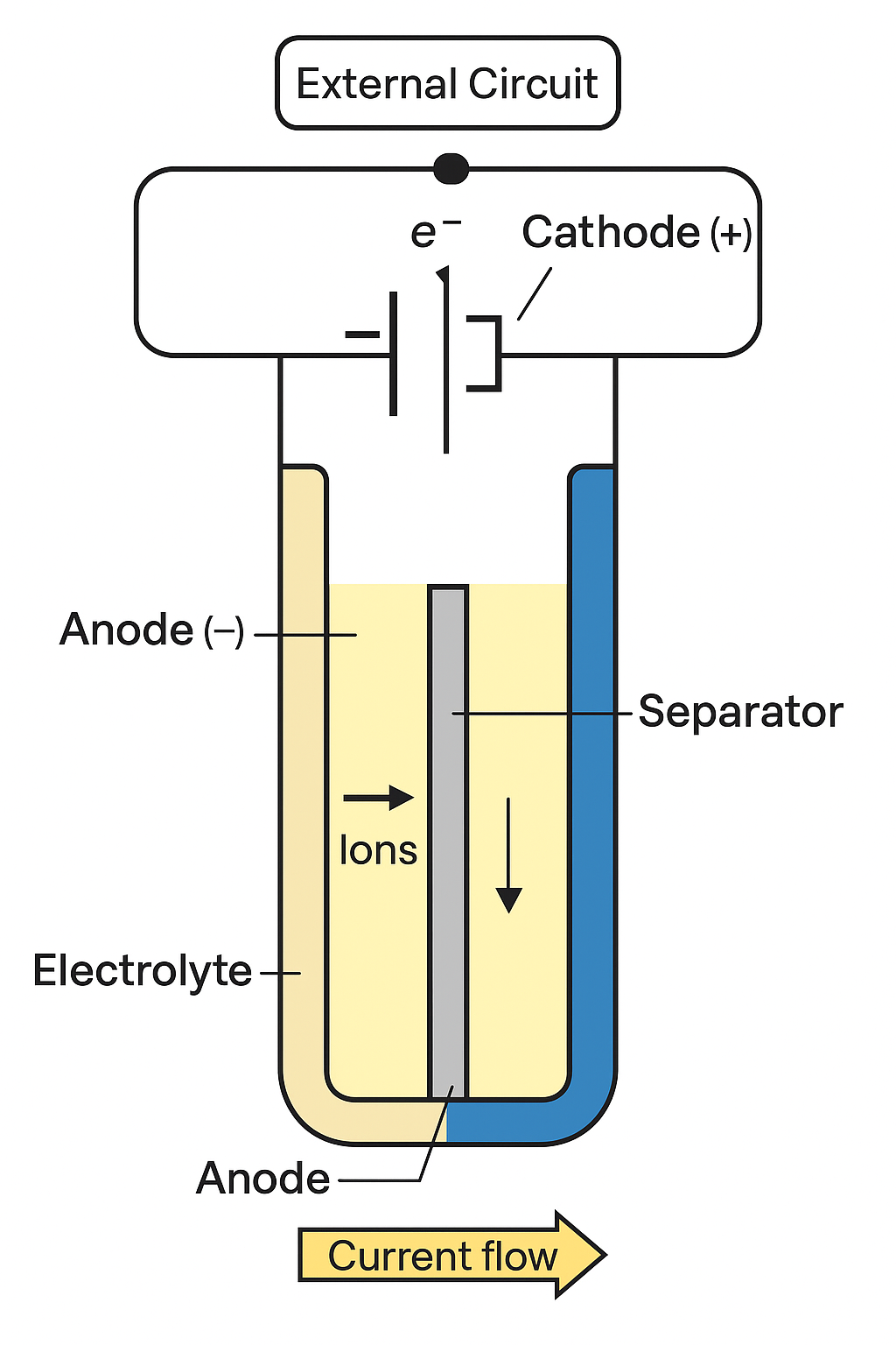
A battery is a device that converts chemical energy into electrical energy. It is made up of one or more electrochemical cells. Each cell contains several key components that work together to produce electric current.
Components of a Battery
| Component | Function |
|---|---|
| Anode (-) | Negative terminal where oxidation occurs. Electrons are released. |
| Cathode (+) | Positive terminal where reduction occurs. Electrons are accepted. |
| Electrolyte | Allows movement of ions between anode and cathode. Maintains charge balance. |
| Separator | Keeps anode and cathode apart. Allows ion flow but prevents short circuit. |
| External Circuit | Path through which electrons flow from anode to cathode (e.g., wire connected to a device). |
How a Battery Works
- A chemical reaction causes electrons to be released at the anode (oxidation).
- These electrons travel through the external wire (current flows).
- They enter the cathode where they are accepted (reduction).
- At the same time, ions move through the electrolyte inside the battery to maintain neutrality.
Example: Dry Cell Battery
- Anode: Zinc casing (also acts as container)
- Cathode: Carbon rod surrounded by manganese dioxide
- Electrolyte: Paste of ammonium chloride and zinc chloride
Used in: Remote controls, clocks, torches, toys
Resistance and Ohm's Law
Resistance is the opposition that a material offers to the flow of electric current. When an electric current passes through a conductor, the free electrons collide with the atoms of the material, causing energy loss in the form of heat. This opposition to the flow of electrons is called resistance. It depends on several factors such as the material of the conductor, its length, cross-sectional area, and temperature. Resistance is denoted by the letter R and is measured in ohms (O). Conductors like copper have low resistance and allow current to flow easily, while insulators like rubber have high resistance and restrict current flow. It is measured in ohms and represented by the symbol "R". Resistance determines how much current will flow through a conductor for a given voltage.
Formula: R = V/I
- R = Resistance (ohms)
- V = Voltage (volts)
- I = Current (amperes)
Ohm's Law
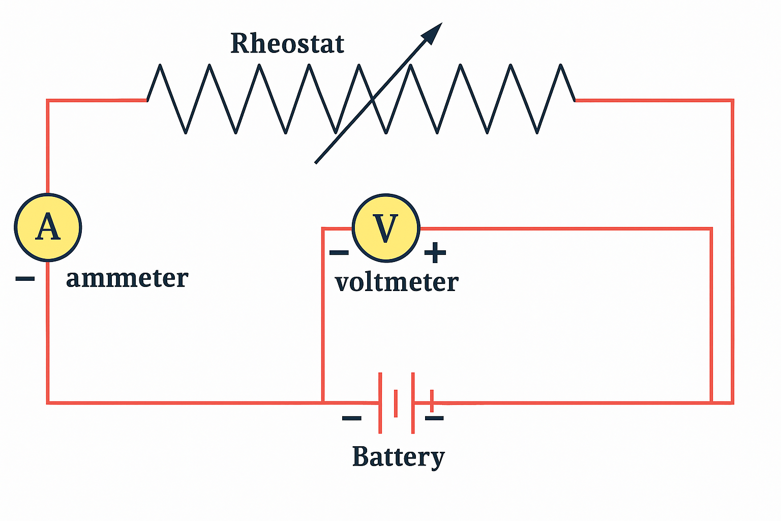
Ohm's Law is a fundamental principle in electricity that states the electric current flowing through a conductor is directly proportional to the potential difference (voltage) across its ends, provided the temperature remains constant. This means that if the voltage increases, the current increases, and if the voltage decreases, the current also decreases, assuming resistance stays the same. Mathematically, it is expressed as V = I X R, where V is the voltage in volts, I is the current in amperes, and R is the resistance in ohms. Ohm’s Law is widely used in electrical circuits to calculate voltage, current, or resistance and is essential for designing and analyzing electronic devices and systems.
Mathematical Expression: V = I X R
Example:
If a 2 ampere current flows through a 3 ohm resistor, the voltage across it is:
V = I X R = 2 X 3 = 6 volts
Factors Affecting Resistance
- Length of the conductor: The longer the wire, the greater the resistance, as electrons have more material to pass through.
- Cross-sectional area (thickness): Thicker wires offer less resistance because there is more space for electrons to flow.
- Material of the conductor: Different materials have different resistivities. For example, copper and silver have low resistance, while rubber and plastic have very high resistance.
- Temperature: In most metals, resistance increases with temperature due to increased vibration of atoms, which obstructs the flow of electrons.
Applications of Ohm's Law:
Ohms Law is widely used in both theoretical and practical aspects of electricity. It helps engineers and electricians calculate the correct amount of current, voltage, or resistance in electrical circuits. This is crucial for designing safe and efficient electrical systems in homes, schools, industries, and electronic devices. It is also used in selecting the appropriate resistor values in circuits and for testing electrical appliances. In troubleshooting, this law helps to detect faults like short circuits or broken connections by comparing actual values with expected ones. Overall, it forms the foundation for understanding and working with electric circuits.
Resistivity
Resistivity is the resistance of a wire of of unit length (1 meter) and unit cross-sectional area (1 square meter). It is he basic property of a material, independent of its size or shape. A high resistivity value indicates that the material strongly resists the flow of electric current, while a low value indicates that it conducts electricity well. Resistivity ca be calculated by using formula is hp=RA/t
Resistors in Series and Parallel
🔗 Resistors in Series
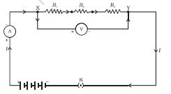
When resistors are connected end-to-end so that the current flows through one after the other, they are said to be in series. The total or equivalent resistance is the sum of individual resistances.
Formula: Rtotal = R1 + R2 + R3 + ...
- Same current flows through all resistors.
- Voltage is divided among resistors.
- If one resistor breaks, the whole circuit is interrupted.
⚡ Resistors in Parallel
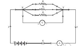
When resistors are connected such that the ends of all resistors are connected together at both sides, they are in parallel. The reciprocal of total resistance is the sum of the reciprocals of individual resistances. Understanding these connections helps in designing efficient circuits and choosing appropriate configurations.
Formula: 1/Rtotal = 1/R1 + 1/R2 + 1/R3 + ...
- Same voltage across all resistors.
- Current is divided among branches.
- If one resistor fails, current can still flow through others.
📊 Comparison Table
| Feature | Series Connection | Parallel Connection |
|---|---|---|
| Total Resistance | Increases (sum of resistors) | Decreases (inverse sum) |
| Current Flow | Same through all resistors | Divides among resistors |
| Voltage Distribution | Divided among resistors | Same across all resistors |
| If One Resistor Fails | Whole circuit breaks | Other resistors still work |
| Application | Bulbs in decorative lights | Household wiring, appliances |
Relationship Between Electricity and Power
Electricity refers to the flow of electric charge, typically through conductors like wires. It is measured in terms of current (amperes) and voltage (volts).
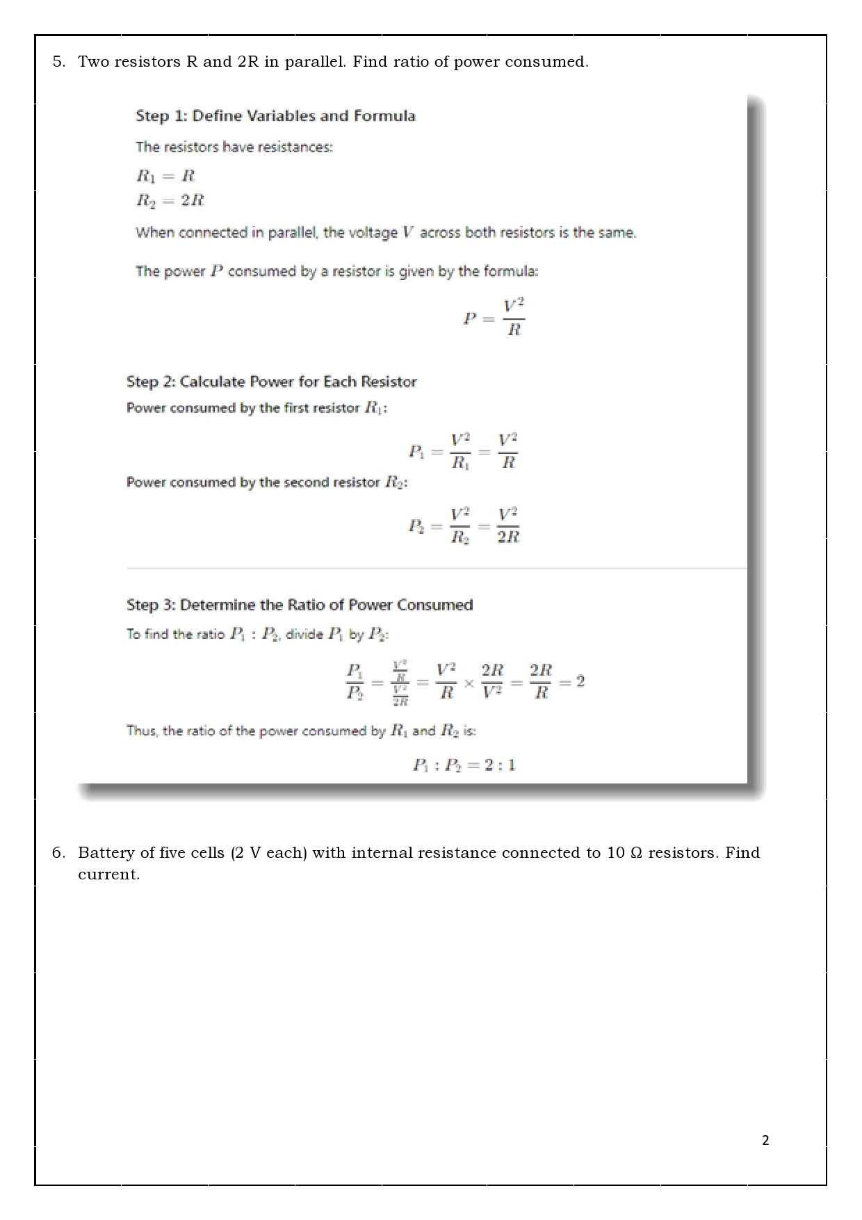
Power is the rate at which electrical energy is consumed or generated. It is measured in watts (W).
Mathematical Relationship:
Power (P) = Voltage (V) × Current (I)
This means that the more current flows or the higher the voltage, the more power is used or produced.
Example: If a device operates at 230 volts and draws 2 amps of current, then:
P = V × I = 230V × 2A = 460W
This simple formula helps us understand the relationship between the flow of electricity and the energy used or supplied in an electrical system.
Conversion of Units of Electric Current
Electric current is measured in amperes (A), but sometimes we use other related units depending on the situation.
| Unit | Symbol | Equivalent in Amperes (A) |
|---|---|---|
| Milliampere | mA | 1 mA = 0.001 A |
| Microampere | μA | 1 μA = 0.000001 A |
| Kiloampere | kA | 1 kA = 1000 A |
Example: If a circuit uses 2500 mA, it means:
2500 mA = 2500 × 0.001 = 2.5 A
Use the conversion factors to switch between different units of electric current depending on your measurement scale.
Previous year Board papers with solutions
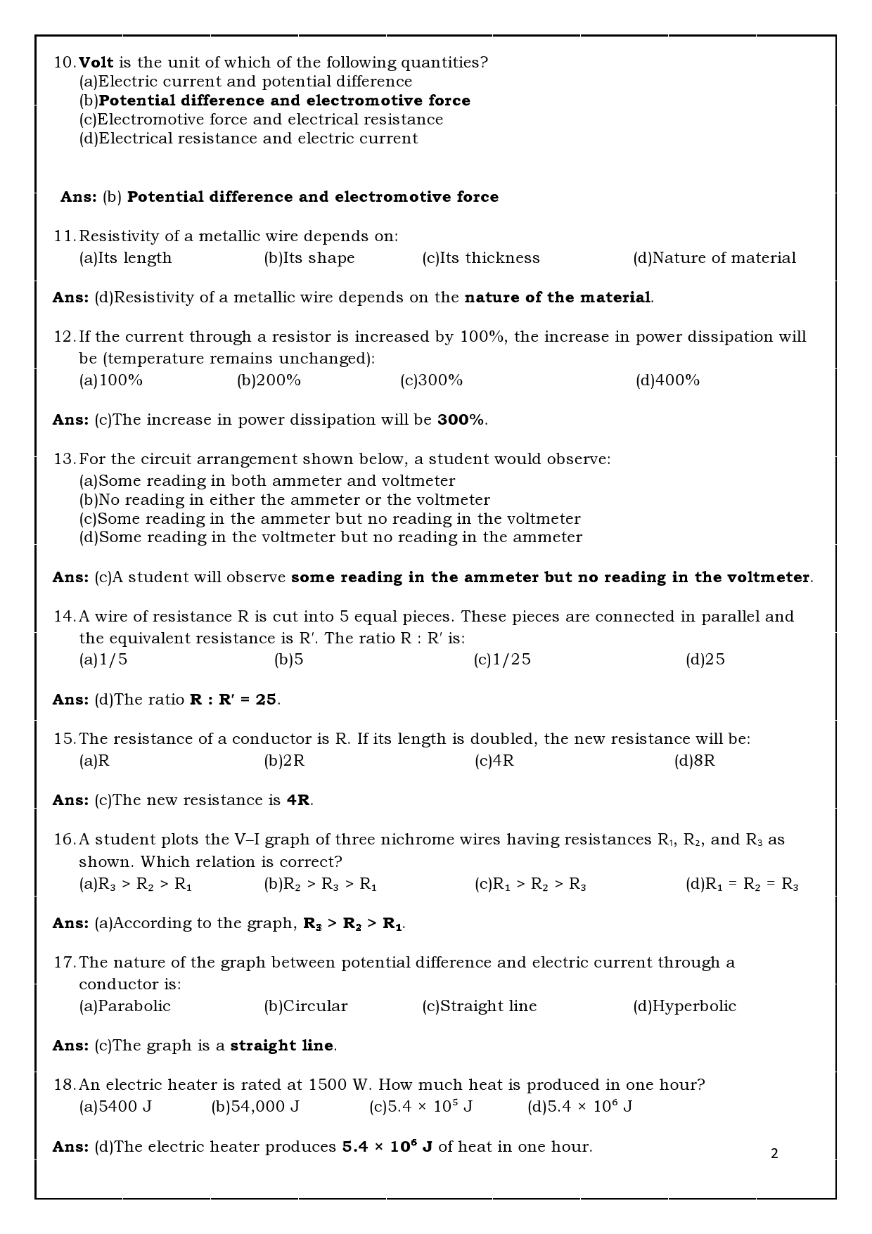
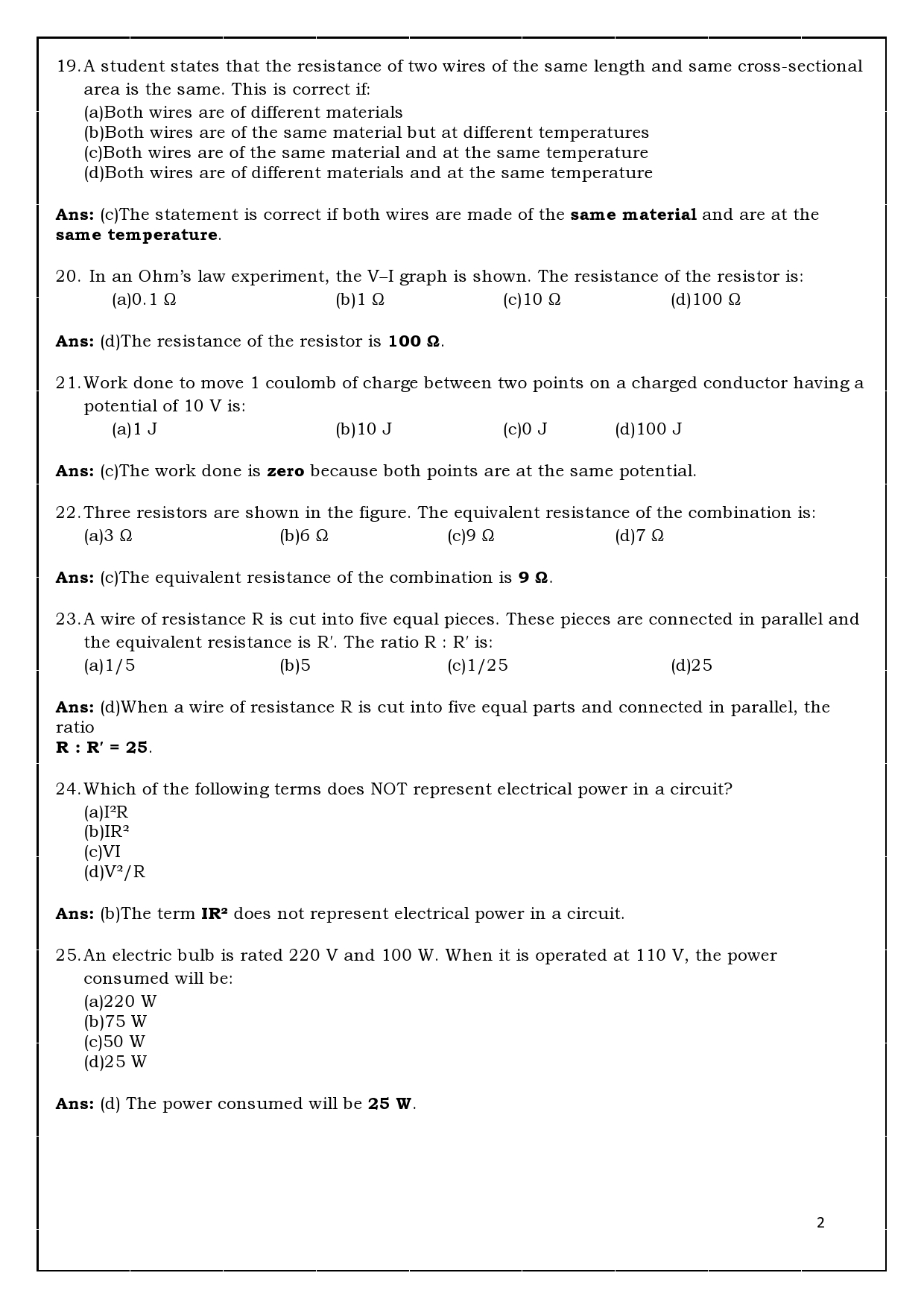
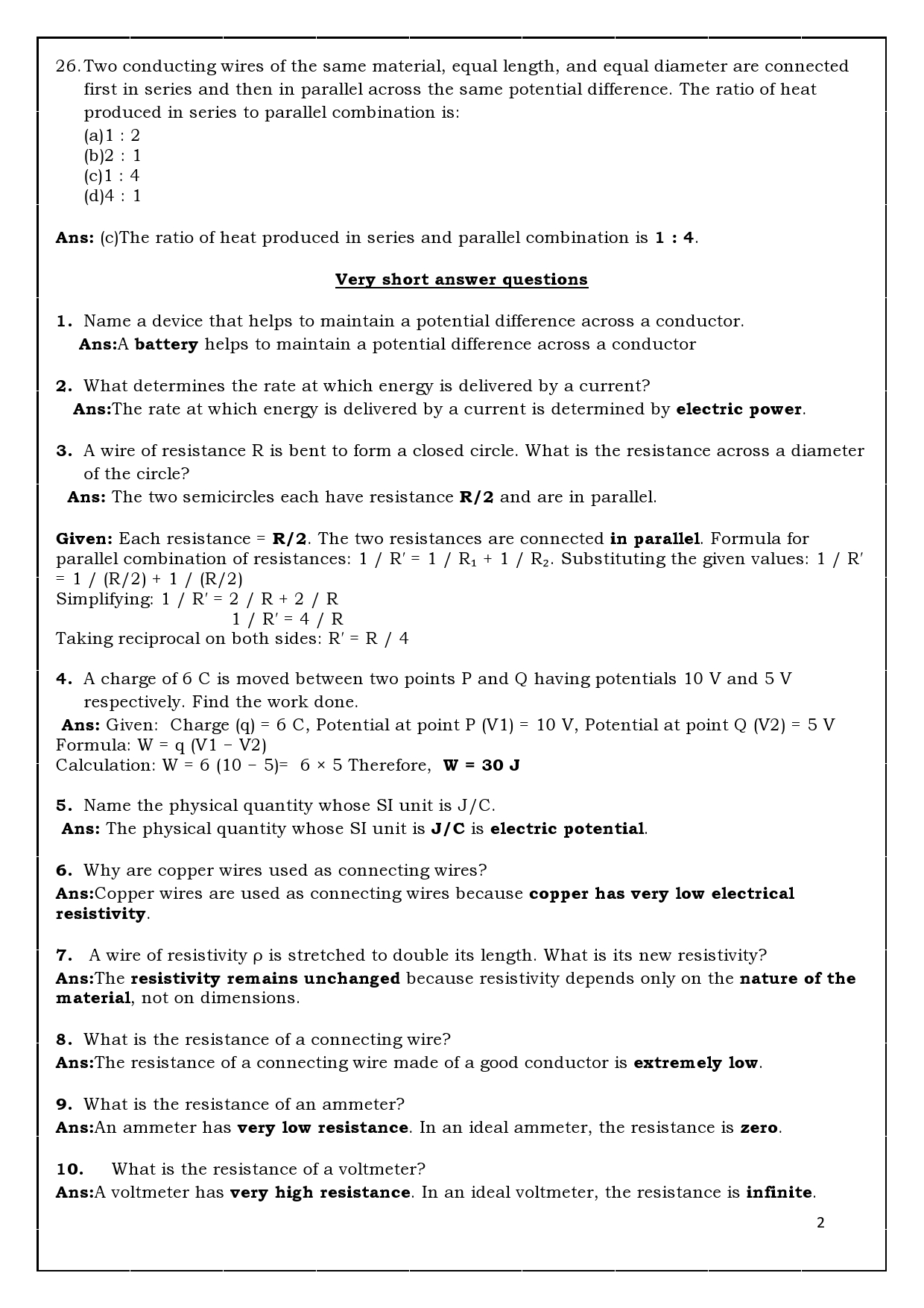
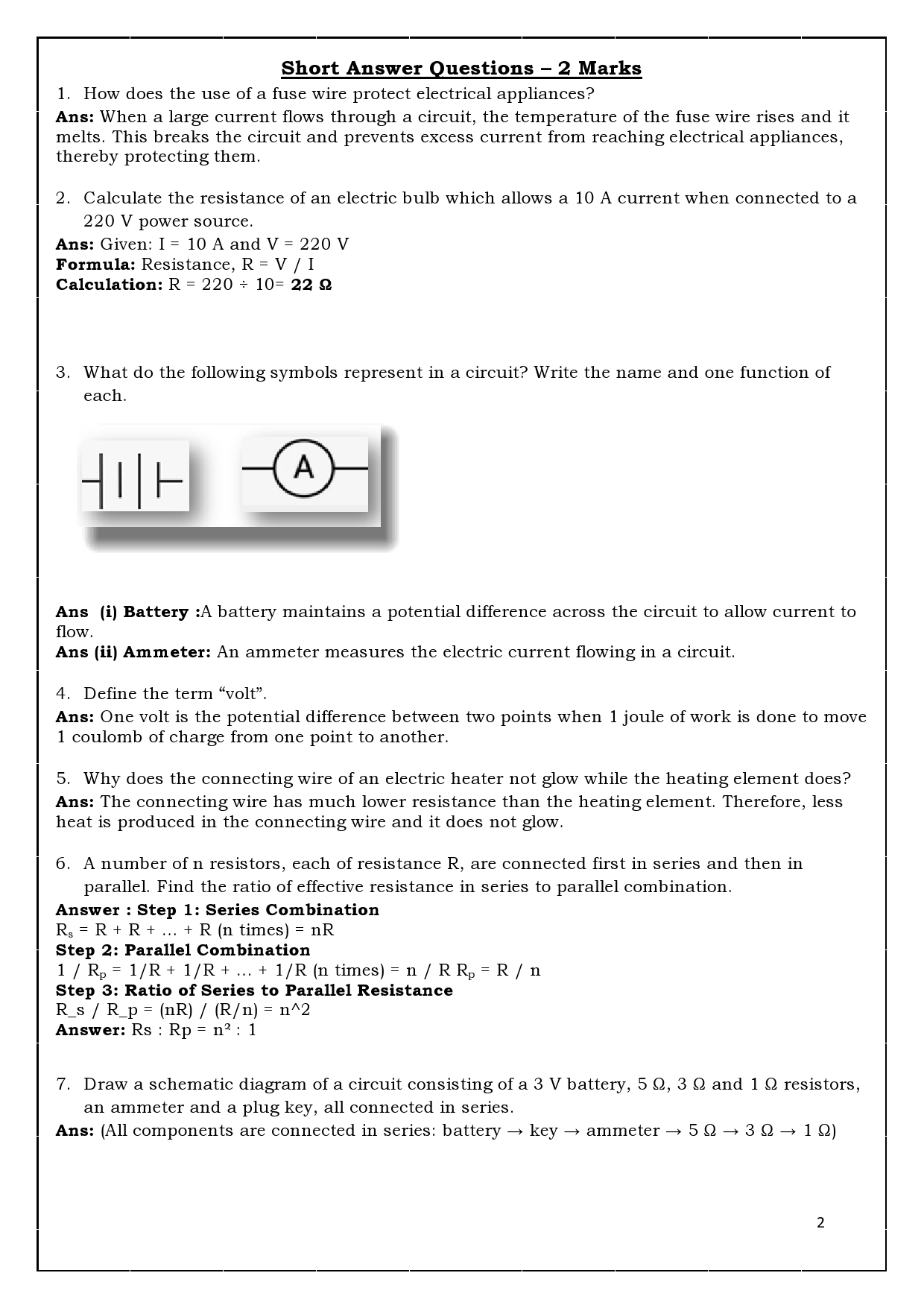
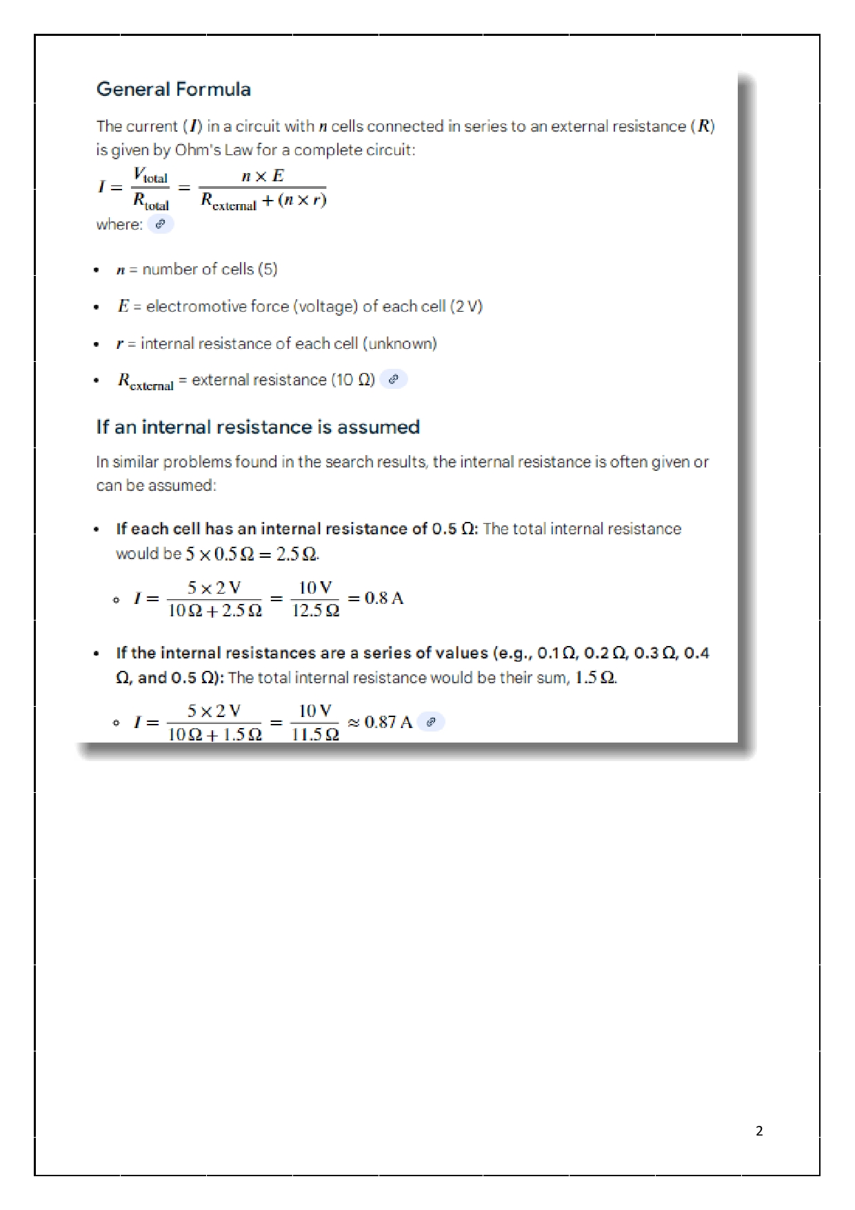
Lesson Based Assessment(LBA Solutions)
|
Difficultylevel |
No.of Questions |
No.ofMarks |
Percentage |
|
Easy |
32 |
43 |
30% |
|
Average |
43 |
71 |
50% |
|
Difficulty |
19 |
28 |
20% |
lesson Objectives
- Electric current, electric circuit, electric potential, potential difference, electric charge, electric capacity and their SI unit
- Electric circuit and their symbols
- Ohm’s law and Joule’s law of heat generation
- Resistance of a conductor, types of resistor circuits, advantages and disadvantages of series and parallel circuit•
- Series and parallel circuit connection diagrams
- Thermal effects of electric current and its practical applications
I. Multiple Choice Questions
Instructions: Choose the correct option.
-
SI unit of electric current is (MQP3-25)
A. Ampere (A)
B. Ohm (Ω)
C. Volt (V)
D. Watt (W) -
SI unit of power is
A. Ampere (A)
B. Ohm (Ω)
C. Volt (V)
D. Watt (W) -
The property of a conductor that opposes the flow of charges is called
A. Electric current
B. Electric potential difference
C. Electric resistance
D. Electric power -
Rate of flow of electric charges is called
A. Electric current
B. Electric potential
C. Electric resistance
D. Electric power -
The work done in bringing a unit charge from one point to another is called
A. Electric current
B. Electric potential
C. Electric resistance
D. Electric power -
Rate of consumption of energy is called
A. Electric current
B. Electric potential difference
C. Electric resistance
D. Electric power -
Symbol used to represent an electric cell is

-
Symbol for a closed circuit in an electric circuit is

-
Symbol used to represent a dry cell in a circuit is

-
The given symbol in an electric circuit represents
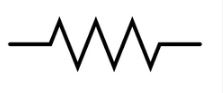 A. Resistor
B. Ammeter
C. Dry cell
D. Voltmeter -
In an electric circuit, the ammeter and voltmeter are connected as
A. Both in parallel
B. Both in series
C. Ammeter in series and voltmeter in parallel
D. Ammeter in parallel and voltmeter in series -
Formula not applicable for Ohm’s law is
A. V / I = R
B. V = IR
C. I = V / R
D. V = I / R -
Net resistance when 2 Ω and 4 Ω resistors are connected in series and a 4 Ω resistor in parallel is
A. 2 Ω
B. 2.4 Ω
C. 4 Ω
D. 10 Ω -
A 27 Ω conductor is cut into three equal parts and connected in parallel. Total resistance is (MAIN-2019)
A. 6 Ω
B. 3 Ω
C. 9 Ω
D. 27 Ω -
Net resistance when 2 Ω and 3 Ω resistors are connected in parallel and a 2 Ω resistor in series is
A. 3.2 Ω
B. 2 Ω
C. 3 Ω
D. 1 Ω -
A wire of resistance R is cut into three equal parts and connected in parallel. The ratio R : R₁ is (SEP-2019)
A. 1 : 3
B. 9 : 1
C. 1 : 9
D. 3 : 1 -
An electric circuit of 6 V does work of 24 J. The charge flown is
A. 2 C
B. 4 C
C. 6 C
D. 10 C -
If 10 C charge flows through a circuit of 4 V, the work done is
A. 10 J
B. 20 J
C. 40 J
D. 30 J -
A 30 Ω bulb and 6 Ω conductor are connected in series to a 9 V battery. The total current is (MAIN-2021)
A. 4 A
B. 36 A
C. 0.25 A
D. 0.6 A -
In a conductor, if current is 4 A and resistance is 12 Ω, when resistance is doubled the current becomes
A. 2 A
B. 3 A
C. 4 A
D. 8 A -
The resistance of a conductor of length 4l is 4 Ω. If the length becomes 2l, the resistance will be
A. 0.5 Ω
B. 2 Ω
C. 4 Ω
D. 8 Ω -
Device used to measure potential difference is
A. Galvanometer
B. Ammeter
C. Speedometer
D. Voltmeter -
The formula for electric power is
A. P = I × R
B. P = VI
C. P = V × R
D. V × R = P -
The correct statement related to resistance is
A. Directly proportional to potential difference but inversely proportional to current
B. Inversely proportional to potential difference but directly proportional to current
C. Inversely proportional to both potential difference and current
D. Directly proportional to both potential difference and current -
The safety device used to avoid short circuit is
A. Fuse
B. Switch
C. Resistor
D. Transistor -
The formula used to measure electric energy is
A. E = VIt
B. E = Pt
C. E = RCt
D. E = Vt -
A device used to change resistance in an electric circuit is (MAIN-2021)
A. Voltameter
B. Ammeter
C. Galvanometer
D. Rheostat -
Ohm is the SI unit of (MAIN-2021)
A. Electric potential difference
B. Resistance
C. Electric current
D. Electric charge -
The metal used in the filament of an electric bulb is (MAIN-2021)
A. Manganese
B. Tungsten
C. Nickel
D. Chromium -
SI unit of electric potential difference is (SEP-2021)
A. Volt
B. Ampere
C. Ohm
D. Coulomb -
The resistance of an electric heater coil is 110 Ω. The current drawn from a 220 V source is (SEP-2021)
A. 0.5 A
B. 0.11 A
C. 2 A
D. 3 A -
A device that is connected in series in an electric circuit is (SEP-2021)
A. Voltmeter
B. Bar magnet
C. Turbine
D. Ammeter -
The function of fuse in an electric circuit is that it (SEP-2021)
A. Reverses the direction of current
B. Shows direction of current
C. Measures potential difference
D. Protects electrical appliances -
The correct relationship between potential difference, current and resistance is (MAIN-2022)
A. I = V / R
B. I = VR
C. V = RI
D. R = IV -
The device used to measure the rate of current in a circuit is (MAIN-2023)
A. Ammeter
B. Voltmeter
C. Galvanometer
D. Battery -
The SI unit of resistivity is (SEP-2022)
A. Ohm
B. Volt
C. Watt
D. Ohm-metre -
Ohm’s law gives the relationship between
A. Potential difference and electric charge
B. Potential difference and resistance
C. Electric current and potential difference
D. Electric current and electric power -
Four resistors of 2 Ω each are connected in series to get Rs and in parallel to get Rp. The ratio Rs : Rp is (MAIN-2024)
A. 16 : 1
B. 2 : 1
C. 4 : 1
D. 8 : 1 -
SI unit of electric charge is
A. Coulomb
B. Ampere
C. Joule
D. Volt
I. Multiple Choice Questions – ANSWERS
- A – Ampere
- D – Watt
- C – Electric resistance
- A – Electric current
- B – Electric potential
- D – Electric power
- A – ⎯| |⎯
- A – ⎯o—o⎯
- A – ⎯| |⎯
- B – Ammeter
- C – Ammeter in series and voltmeter in parallel
- D – V = I / R
- B – 2.4 Ω
- B – 3 Ω
- A – 3.2 Ω
- B – 9 : 1
- B – 4 C
- C – 40 J
- C – 0.25 A
- A – 2 A
- B – 2 Ω
- D – Voltmeter
- B – P = VI
- A – Directly proportional to V, inversely proportional to I
- A – Fuse
- A – E = VIt
- D – Rheostat
- B – Resistance
- B – Tungsten
- A – Volt
- C – 2 A
- D – Ammeter
- D – Protects electrical appliances
- A – I = V / R
- A – Ammeter
- D – Ohm-metre
- C – Electric current and potential difference
- A – 16 : 1
- A – Coulomb
One Mark Questions
- Two connecting wires of same length and same diameter are made up of copper and iron. Among these two which is having more resistance? (A)
- Two students A and B conduct experiment connecting R1 and R2 resistors in series and parallel and plot the graph of V-I as below. Who has plotted the graph correctly?
- How many joules does 1 unit (Kwh) have? (E)
- Define 1 ohm? (E)
- What is the meaning of 1 Ampere? (E)
- How many electrons does 1 coulomb ( C ) have? (E)
- ― The potential difference between two points of connecting wire is 1 volt‖ define the statement. (E)
- Name the devices used to measure Electric current and potential difference. (E)
- What is the Resistance of a conductor? (E)
- When the resistance of a conductor did becomes 1 Ω? (E)
- Why the Nitrogen or Argon gas is filled inside the electric bulb? (A)
- Name the commercial unit of electricity. (E)
- How is fuse connected in an electric circuit? (E)
- What are the uses of fuse in domestic electric circuit? (E)
- Why Tungsten wires are used in electric bulb? (E)
- Write the symbols for -A wire joint and an electric bulb
- What are the reasons for occurring overload in an electric circuit ? (SEP- 2022) (A)
- Write the symbols rheostat and wires crossing without joining in a circuit.
- Write the symbols of electric cell and voltmeter used in an electric circuit.
- Draw the symbol diagram of two electric cells connected in series in an electric circuit.
- Can an electric heater of 2KW capacity be connected to an electric circuit of 15A rating, 220V potential difference? Justify your answer. (Mar/Apr-2024)
Key Ansers
- Ironhas more resistance than copper (because iron has higher resistivity).
- Student Ahas plotted the graph correctly. (V–I graph is a straight line passing through the origin.)
- 1 unit (1 kWh) = 3.6 × 10⁶joules
- 1 ohmis the resistance of a conductor when a potential difference of 1 volt produces a current of 1 ampere through it.
- 1 ampereis the current when 1 coulomb of charge flows through a conductor in 1 second.
- 1 coulomb = 6.25 × 10¹⁸electrons
- The potential difference between two points is 1 voltif 1 joule of work is done in moving 1 coulomb of charge between them.
- Electric current → Ammeter. Potential difference → Voltmeter
- Resistance of a conductor is the opposition offered to the flow of electric current.
- The resistance of a conductor becomes 1 ohmwhen 1 ampere current flowsthrough it on applying 1 volt potential difference.
- Nitrogen or argon gas is filled in an electric bulb to prevent oxidation of the tungsten filament and increase its life.
- The commercial unit of electricity is kilowatt-hour (kWh).
- A fuse is always connected in seriesin an electric circuit.
- Fuse is used to protect electrical appliancesby breaking the circuit during overload or short circuit.
- Tungsten is used because it has high melting point and high resistivity.
- i) Wire joint→ ● ii) Electric bulb→ ⊗
- Overloading occurs due to: Connecting too many appliancesto a single socket and using high-power devicessimultaneously
- i) Rheostat→ Variable resistance symbol ii) Wires crossing without joining→ Crossing lines without dot
- i) Electric cell→ ⎯| |⎯ ii) Voltmeter→ Ⓥ
- Two electric cells connected in series → ⎯| |⎯| |⎯
- No. Current drawn = P / V = 2000 / 220 ≈ 1 A
Though current is less than 15 A, such heaters require dedicated circuits for safety, hence not advisable.
Two Mark Questions
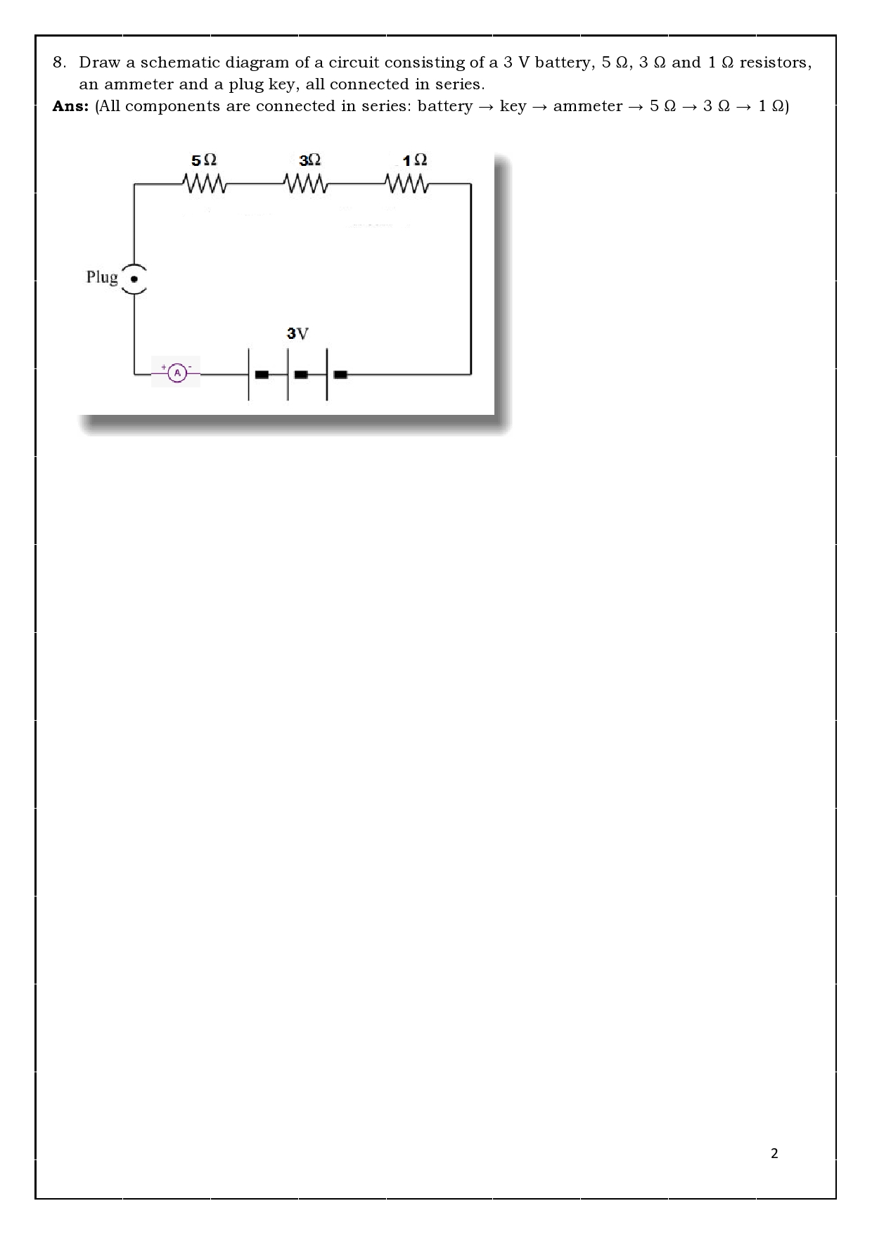
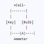
- What is electric circuit? Write the schematic diagram of an electric circuit comprising cell, electric bulb, ammeter & plug key. (Main-2022) (E)
- In which of the below devices the electric energy is used maximum?
|
Devices |
Time used |
Power |
|
TV |
1 Hour |
250 Wats |
|
Toaster |
10 Minutes |
1300 Wats |
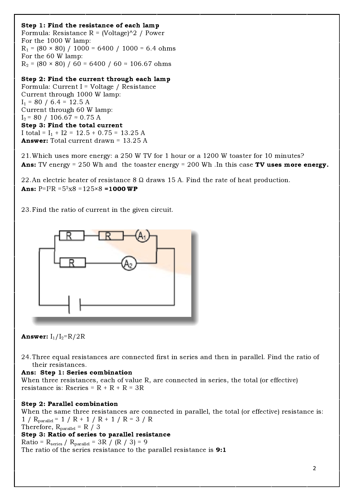
- 2 Ω, 3 Ω & 4 Ω resistors are connected in parallel & then in series. In which connection does their total resistance will be less than their resistance?
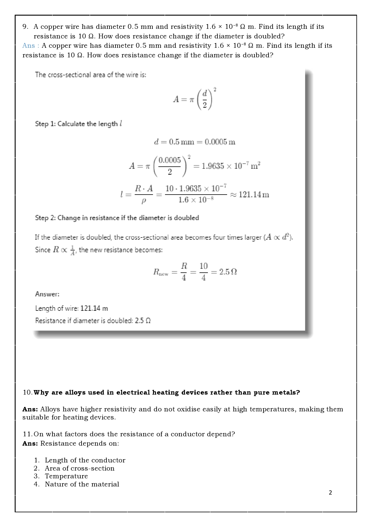
- Resistivity of copper 1.63 x 10⁻⁸ Ωm & its cross section is 10.3 x 10⁻⁵cm3 . Calculate the length of wire needed to make a coil of 10 Ω resistance.
- Electrical resistivity of some substances at 200 c is given below.
|
Materials |
Resistivity |
|
silver |
1.60 X 10⁻⁸ Ωm |
|
copper |
1.63 X 10⁻⁸ Ωm |
|
tungsten |
5.2 X 10⁻⁸ Ωm |
|
nichrome |
100 X 10-6 Ωm |
- Among silver and copper which is the good conductor. Why?
- Which material is suitable for electrical heating. Why?
- Explain the working principle of electric fuse.
- Define Electric resistance and resistivity . How are they interrelated?
- Explain the working mechanism of an Electric bulb.
- In domestic electric circuit it is suitable to connect electrical devices in parallel. Mention two reasons for it.
- State Joule‘s law of heating. How fuse is connected in an electrical circuit. Mention the Metal used in a filaments of an electric bulb and the gas filled in the bulb (MARCH-2023)
- A bulb is marked 220 V and 40 W. Calculate the current flowing through the bulb and it‘s resistance. (SEP-2019
- The resistivity of manganese wire of length 1 m is 1•84 × 10-2 m at 20°C. If the diameter of the wire is 3 × 10⁻⁴ Ω m, what will be the resistance of the wire at that temperature? (MAIN- 2020)
- Observe the given circuit:
- Calculate the total resistance in the circuit and the total current flowing in the circuit. 78. An electric bulb with a resistance of 50 Ω is connected to 10 V battery in an electric circuit. Calculate the electric current flowing through the electric bulb and electric power of the bulb.
- 1000 J of heat is produced each 2 seconds in a 5 Ω resistor. Find the potential difference across the resistor. (SEP-2023)
- A wire of given material having length ‗l‘ and area of cross section ‗A‘ has a resistance of ‗4 Ω‘. Find the resistance of another wire of the same material having length l/2 and area of cross-section ‗2A‘. (SEP-2023)
- Placing a fuse in domestic electric circuits is essential. Why ? Explain.
Key Answers
- An electric circuitis a closed conducting path through which electric current flows. Schematic diagram
- Energy used = Power × Time. For TV = 250 W × 1 h = 250 Wh
For Toaster = 1300 W × (10/60) h ≈ 217 Wh. Therefore, TV uses maximum electric energy. - The total resistance is less than individual resistances when resistors are connected in parallel, because current gets multiple paths.
- Given: R = 10 Ω, ρ = 1.63 × 10⁻⁸ Ωm. Area A = 10.3 × 10⁻⁵ cm² = 10.3 × 10⁻⁹ m². Formula R = ϼ l/ A.
- Therefore l = R A/ ϼ = 20 X 10.3 X 10-5X 10-3 /1.63 X
- = 20 X 10.3 X 10-8 /1.63 X 10-8
- =126.38 m.
- So, the length of wire is 38 m
- Silveris a better conductor because it has lower resistivity. Nichrome is suitable for heating because it has high resistivity and high melting point.
- An electric fuseworks on the heating effect of electric current.
When excess current flows, the fuse wire melts and breaks the circuit, protecting appliances. - It is the propeRTy of the conductor to resist the flow of charges through it.
- It is the characteristic propeRTy of the material which is a constant of propoRTionality. Resistance measures how much it opposes the flow of current . Whereas resistivity is an intrinsic propeRTy of material.
- In an electric bulb, current heats the tungsten filamentto white-hot state, producing light. The ineRT gas prevents oxidation of the filament.
- Electrical devices are connected in parallelbecause:
- Each device gets same voltage
- Failure of one device does not affect others
- Joule’s law of heating: H=I2Statement:The heat produced in a conductor due to the flow of electric current is directly propoRTional to the square of the current (I²), the resistance (R) of the conductor, and the time (t) for which the current flows. Fuse is connected in series and the filament metal is Tungsten. Gas filled → Argon / Nitrogen inside the filament.
- Given: V = 220 V, P = 40 W
- I=PV
- =40X220
- =1210Ω
- Given, resistivity (ρ) = 1.84 × 10⁻⁶ ohm metre. Length (L) = 1 metre and the diameter (d) = 3 × 10⁻⁴ metre
- Radius (r) = d / 2
- r = 1.5 × 10⁻⁴ metre
- As per the formula :Resistance R = ρL / A and area “A” = πr²
- A = 3.14 × (1.5 × 10⁻⁴) × (1.5 × 10⁻⁴)
- A = 7.07 × 10⁻⁸ square metre
- R = (1.84 × 10⁻⁶ × 1) / (7.07 × 10⁻⁸)
- R ≈ 26 ohms
- Given: R1= 5 ohm, R2= 4 ohm, R3 = 12 ohm, V = 24 volt Assumption: R1 and R2 are connected in parallel, and this combination is connected in series with R3
Step 1: Find equivalent resistance of R1 and R2 (parallel)
- Formula:
1 / Rp = 1 / R1 + 1 / R2 - 1 / Rp = 1 / 5 + 1 / 4
- 1 / Rp = (4 + 5) / 20
- 1 / Rp = 9 / 20
- Rp = 20 / 9 ohm
- Rp ≈ 2.22 ohm
Step 2: Find total resistance of the circuit
- RT = Rp + R3
- RT = 2.22 + 12
- RT = 14.22 ohm
Step 3: Find total current using Ohm’s Law
- Formula: I = V / R
- I = 24 / 14.22
- I ≈ 1.69 ampere
Answer: Total resistance of the circuit = 14.22 ohm. Total current flowing through the circuit = 1.69 ampere
- Given:Heat produced, H = 1000 J, Time, t = 2 s, Resistance, R = 5 ohm
Step 1: Calculate Power
- Formula: P = H / t
- P = 1000 / 2
- P = 500 W
Step 2: Calculate Potential Difference
- Formula: P = V² / R
- V² = P × R
- V² = 500 × 5
- V² = 2500
- V = √2500= 50V
Answer: Potential difference across the resistor = 50 V
3 Mark Questions
- The value of resistors R1 ,R2& R3 are 5 Ω, 10 Ω & 30 Ω. If they are connected to dry cell of 12V potential difference ,calculate i) Electric current flowing through each resistor ii) Total electric current through circuit. iii) Total resistance of entire circuit.
- A Refrigerator of 400 Watt works 10 hrs daily, an electric fan of 80 Watt works 6 hrs daily and an electric bulb of 18 Watt glows 6 hrs daily. If the rate of per unit is 3 rupees, Then what is the amount of electric bill the owner has to pay in the month of June?
- Among iron, silver and nichrome which one is utilized inside an electric iron box which works on the heating effect of electric current . Justify your answer with 3 reasons.
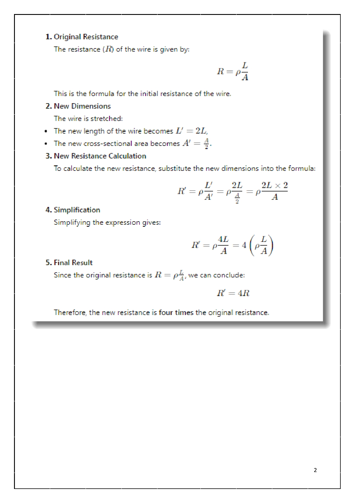
- A connecting wire of 20 Ω resistance is drawn to double its length .Calculate the resistance in new situation. (D)
- State ohm‘s law. (May-2025) (E)
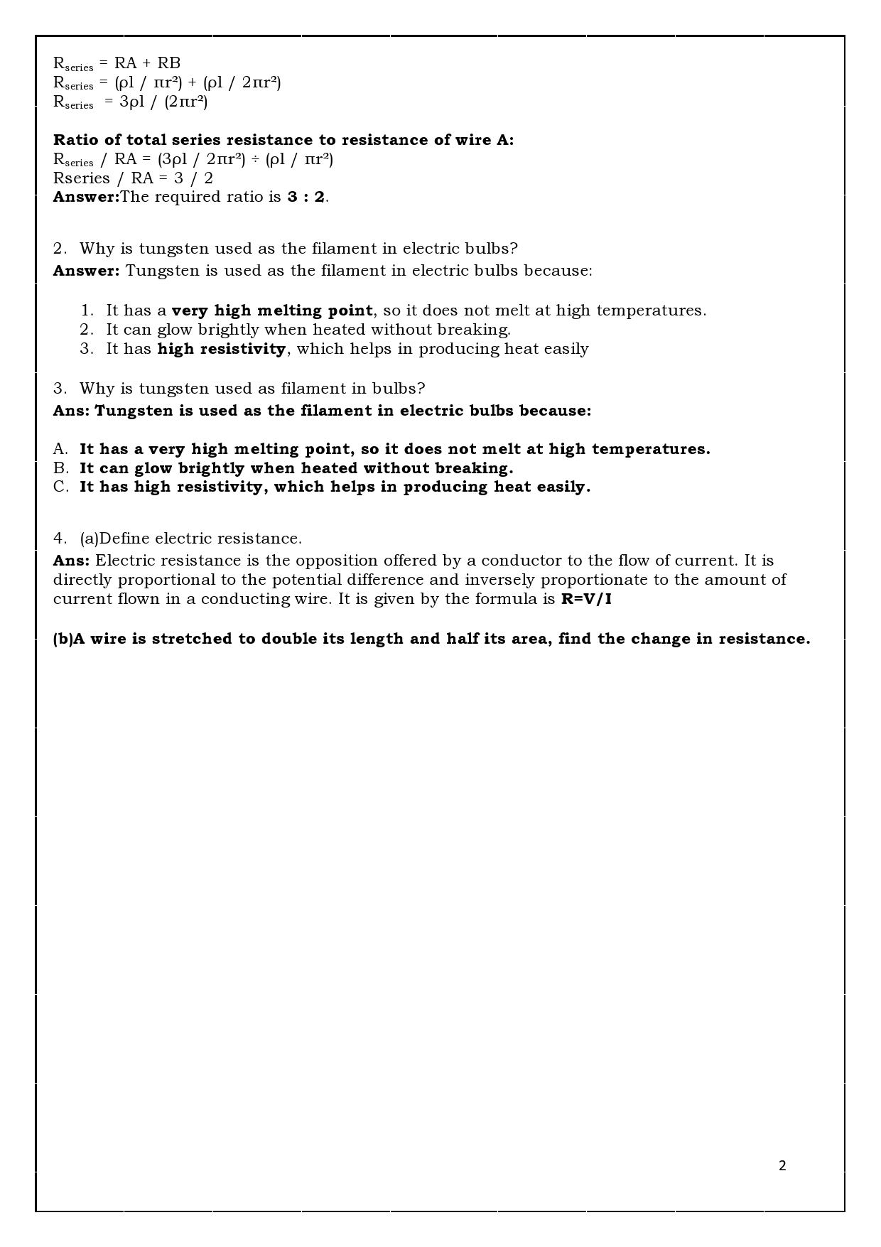
- List the factors on which the resistance of conductor depends. (Main-2023, Main-2024, Sep-19(4M), Sep- 22)
- State Joule‘s law of heating. Explain the working of electric filament bulb. (A)
- The resistors R1 , R2 and R3 have the values 10 Ω, 20 Ω and 60 Ω respectively, which have been parallelly connected to a battery of 24 V in an electric circuit. Then calculate the following (i) The current flowing through each resistor ii) The total current in the circuit. iii) The total resistance of the circuit.
- Resistance of a metal wire of length 2 m is 28 Ω at 20°C. If the diameter of the wire is 0.04 mm then what will be the resistivity of the metal at that temperature? (MQP4-25)
3 Marks Answers
-
The value of resistors R1, R2 & R3 are 5 Ω, 10 Ω & 30 Ω connected to a 12V battery (Series).
Total Resistance:
Rtotal = 5 + 10 + 30 = 45 Ω
Current:
I = V / R = 12 / 45 = 0.27 A
(i) Current through each resistor = 0.27 A
(ii) Total current = 0.27 A
(iii) Total resistance = 45 Ω -
Electric Bill Calculation
Refrigerator: 400W × 10h = 4000Wh = 4 kWh
Fan: 80W × 6h = 480Wh = 0.48 kWh
Bulb: 18W × 6h = 108Wh = 0.108 kWh
Total per day = 4.588 kWh
For 30 days = 137.64 kWh
Bill = 137.64 × 3 = ₹412.92 ≈ ₹413 -
Among iron, silver and nichrome which is used in electric iron?
Answer: Nichrome
Reasons:- High resistivity
- High melting point
- Does not oxidize easily
-
A 20 Ω wire is drawn to double its length. Find new resistance.
When length doubles, area becomes half.
Rnew = 4R
Rnew = 4 × 20 = 80 Ω -
State Ohm’s Law.
At constant temperature, current flowing through a conductor is directly proportional to potential difference across it.
V = IR -
List the factors affecting resistance.
- Length of conductor
- Area of cross section
- Nature of material
- Temperature
-
State Joule’s Law of Heating and explain working of electric bulb.
Joule’s Law: H = I2Rt
Working: Current passes through tungsten filament → due to high resistance it becomes white hot → emits light. -
Parallel Connection (10 Ω, 20 Ω, 60 Ω connected to 24V)
I1 = 24/10 = 2.4 A
I2 = 24/20 = 1.2 A
I3 = 24/60 = 0.4 A
Total Current = 4 A
Total Resistance = 6 Ω -
Resistivity Calculation
Given:
L = 2 m
R = 28 Ω
Diameter = 0.04 mm = 0.00004 m
r = 0.00002 m
A = 3.14 × (2 × 10-5)2
A = 1.256 × 10⁻⁹ m2
ρ = RA / L
ρ = 1.758 × 10⁻⁸ Ωm
Four mark Questions:
- Name any two devices that work on the application of Joule‘s law.
- Why are the alloys like nichrome used in electrical heating devices?
- A bread-toaster rated 350 W is used for 15 hours a day. An electric iron box rated 250 W is used for 5 hours a day. Calculate the cost of using these appliances for 30 days, if the cost of 1 kWh is Rs. 4.
- In which method the resistors R1 and R2 could be connected so that the equivalent resistance of that electric circuit becomes low? What is the change in the value of current in the circuit by this type of connection
- An electric heater connected to a 220 V generator draws a current of 10 A. What is the power of the electric heater ? If it is used for 8 hours a day then calculate the total cost of using it for 30 days at Rs.5 per 1 kWh. (MQP1-25)
Four Mark Answers
-
Name any two devices that work on Joule’s law.
- Electric heater
- Electric iron
-
Why are alloys like nichrome used in heating devices?
- High resistivity
- High melting point
- Does not oxidize easily
- Durable
-
Cost Calculation (Bread toaster & Iron)
Toaster: 350W = 0.35 kW
0.35 × 15 = 5.25 kWh
Iron: 250W = 0.25 kW
0.25 × 5 = 1.25 kWh
Total per day = 6.5 kWh
For 30 days = 195 kWh
Cost = 195 × 4 = ₹780 -
In which method should resistors be connected to reduce resistance?
Parallel connection.
Effect:- Equivalent resistance decreases
- Current increases
-
Electric Heater Calculation
P = VI = 220 × 10 = 2200 W = 2.2 kW
Energy per day = 17.6 kWh
For 30 days = 528 kWh
Cost = 528 × 5 = ₹2640